Human-like touch sensing is challenging: human skin spans a wide hardness range (≈2A-20A Shore), integrates
thousands of receptors/cm², and endures millions of cycles without tearing. Most robotic skins fail by being
too rigid, too low density, or too fragile. Kind Humanoid set out to build a multilayer
skin system with realistic mechanical response and scalable sensing integration.
The approach: a Dragon Skin FX Pro outer shell for toughness and skin-like feel, a
Flex-Foam VIII core tuned for elasticity and compliance, and embedded electrodes
for capacitive or resistive readout. Beyond fabrication, the project emphasized
repeatable workflows-molds, mixing ratios, demolding protocols-that could scale.
Highlights: Optimized foam mix (1:1.6 A:B) for structure; syringe-injection silicone molds for bubble-free 1 mm sheets;
iterative capacitive/resistive stacks to study hysteresis, latency, and wiring-induced shorts.
Manufacturing
Silicone Layer - Dragon Skin FX Pro (1 mm)
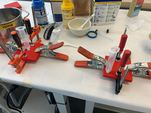
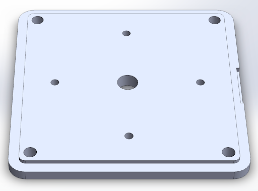
I used 10×10 cm plates with a threaded luer-lock port and 4 vents. Degassing was mandatory: without vacuum,
bubbles formed and weakened the sheet. With slow injection and vent weeping, 1 mm sheets cured consistently.
Failure modes: plunger pressed too fast → side leakage; insufficient release spray → tearing; rushed demold → edge fractures.
Prep: Tap port; clean; light release on wet surfaces; clamp plates; attach luer & 20 mL syringe.
Mix: 1:1 (A:B), e.g., 5 mL + 5 mL; pre-mix ~2 min each addition.
Degas: Vacuum ~3-4 min until bubbling subsides; vent slowly.
Inject: Funnel → syringe; slow plunger for laminar fill until vents weep; wipe excess.
Cure: ~40 min at ≥18 °C; unclamp; free edges; pry at tabs; peel sheet carefully.
Cleanup: IPA wipe; water rinse; tooling reusable.
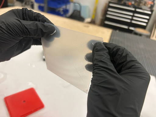
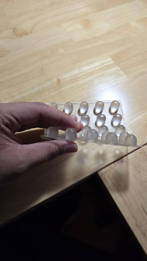
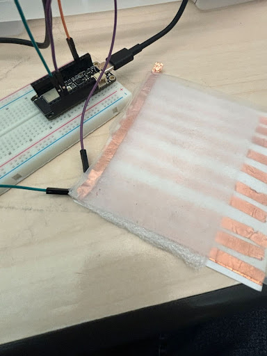
Luer-lock injection system: syringe delivers degassed silicone through threaded port for laminar fill.Cured 1 mm silicone sheet (10×10 cm): bubble-free, uniform thickness, ready for layering.
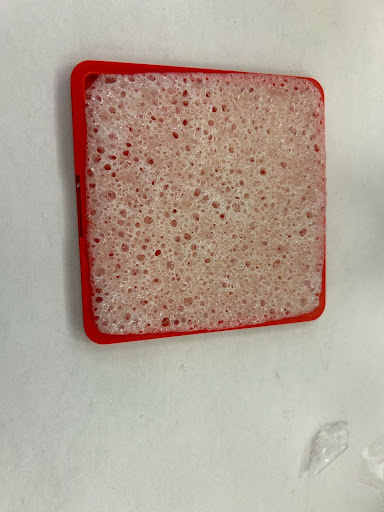
Foam Layer - Flex-Foam VIII (porous elastic)
Default 1:2 ratio produced tacky, dense sheets. I empirically optimized to 1:1.6 A:B, yielding a
non-tacky porous foam with good compliance. Heavy release spray caused crystallized surfaces-only a
light mist worked. Foam expanded ≈7×, so liquid volume had to be carefully planned.
Safety: Part B is hazardous-gloves, goggles, respirator required.
Prep: Tap threaded hole; clean lids; light Ease Release 200 spray on all inner surfaces; distribute with brush.
Calculate: Total foam volume ÷ 7 for expansion; 1:1.6 ratio (A:B), e.g., 10 mL foam = 0.6 mL A + 0.9 mL B.
Mix Part A: Add to bowl; stir thoroughly ~1 min.
Add Part B: Mix quickly 5-10 sec, scrape bottom; 30 sec pot life.
Pour: Swift spiral from top-left inward; brush to distribute; clamp lid.
Cleanup: Acetone/IPA wipe; water rinse; tooling reusable.
Foam mold with heat/pressure relief vents.Flex-Foam VIII, tuned 1:1.6 (A:B).
Materials Selection & Engineering Rationale
Dragon Skin FX Pro - Outer Shell Material Science
Selection Criteria & Bio-Inspired Requirements
The outer layer demanded properties matching human epidermis: friction coefficient approximating fingertips (0.62±0.22 vs. body 0.46±0.15), low shore hardness (~2A for epidermis vs. 20A for full skin stack including muscle), high elongation (matching skin's extensibility), and durability across millions of deformation cycles. Silicone rubbers emerged as the optimal material class due to skin-like friction, deformability, and established use in robotic hands research.
Imperial College's comparative study of commercial silicones established Dragon Skin FX Pro as superior across multiple metrics. Stress-strain characterization revealed highest toughness (area under curve) indicating exceptional fracture resistance, maximum tensile strength ~50 MPa (manufacturer spec: ~500 psi), and greatest stress at fracture among evaluated materials.
Standard silicones exhibit poor fatigue resistance (failure within 10³-10⁴ cycles), but platinum silicone rubbers-Dragon Skin FX Pro's category-achieve orders-of-magnitude improvement (10⁶+ cycles). Platinum-catalyzed cross-linking produces chemically pure product without toxic byproducts, ensuring skin-safe, biocompatible material suitable for human-robot interaction. This purity also maintains excellent electrical insulation across the molecular structure.
Deformability & Compliance
Shore hardness 2A: Matches human epidermis feel; allows conformable contact across varied surface geometries
763% elongation at break: Far exceeds human skin; prevents tearing under extreme deformation
High yield strength: Maintains primarily elastic deformation; minimal permanent plastic deformation under normal use
Moderate Young's modulus: Stress-strain curves show moderate initial slope-sufficiently elastic without being overly compliant (which would reduce force transmission to sensors)
Environmental Stability
Thermal range −60°C to 230°C: Exceptional temperature tolerance enables outdoor/industrial use; silicone's Si-O backbone provides inherent thermal stability; minimal creep at room temperature but subject to creep rupture under sustained stress at high temperatures (similar to biological tissue)
Chemical inertness: Low reactivity across wide pH range; resistant to UV, ozone, moisture; maintains mechanical properties across environmental factors
Platinum cure non-toxicity: No volatile byproducts; food-safe and medical-grade applications; critical for robots interacting with humans
Mechanical Requirements
Project specification: material must withstand 100 N per 1 cm² ≈ 145 psi. Dragon Skin FX Pro's 500 psi tensile strength provides 3.4× safety factor, ensuring reliable operation under maximum loading.
Manufacturability & Scalability
Cost-effective: 55-gallon drum ~\$9,500 (price fluctuates with silicone market); for 6-foot humanoid like Mona, ~½ gallon needed for 1 mm coverage = ~\$85 material cost per robot
Rapid cure: 40-minute cure time at room temperature enables high-throughput production; no specialized heating equipment required
Simple processing: 1:1 mix ratio (A:B); injection-moldable; vacuum-degassable; scales linearly from lab prototypes to manufacturing volumes
Flex-Foam VIII - Compliance Layer Engineering
Selection Rationale
The foam layer requires: lightweight construction (minimizing robotic inertia), large elastic deformation (pressure distribution across sensors), dielectric properties (enabling capacitive sensing), and commercial availability (avoiding complex chemical synthesis). Polyurethane foams outperform silicone foams on weight while maintaining excellent insulative properties and porous structure beneficial for sensor integration.
Material Properties
Density 8 lb/ft³: Extremely lightweight; improves robot dexterity and reduces actuator requirements vs. heavier alternatives
Low Young's modulus: Permits large elastic deformation under compression; distributes applied forces evenly across capacitive sensor array; mimics dermis compliance
Porous structure: Air pockets reduce effective dielectric constant; improves sensitivity of capacitive measurements; provides cushioning similar to biological adipose tissue
High tensile strength: Polyurethane chemistry provides structural integrity despite low density; resists tearing under shear forces
Excellent insulation: Low thermal and electrical conductivity; isolates sensors from environmental noise; maintains stable dielectric properties across temperature range
Formulation Optimization: Why 1:1.6?
Systematic ratio testing revealed critical relationships between Part A:B ratio and material properties:
1:3 (excess Part B): Viscous liquid-like consistency, no structural integrity, failed to cure properly
1:1.6 (optimized): Non-tacky surface, uniform porous structure, good compliance, lighter weight, ideal for sensor integration
1:1.5 (reduced Part B): Improved porosity but compromised structural integrity; foam too weak for repeated compression
1:1 (excess Part A): Phase separation with concentrated Part A pockets; non-uniform properties across sheet; unacceptable for sensing applications
Cost & Accessibility
Flex-Foam VIII trial kit (2 lb) costs \$36, making it extremely affordable for prototyping. No specialized equipment beyond mixing bowls and molds required. Commercial availability eliminates need for complex polyurethane synthesis, enabling rapid iteration and scaling.
Design Iterations & CAD Development
Shear-Sensing Nib Arrays - Approaching Human Tactile Density
Bio-Inspired Design Philosophy
Human fingertips contain approximately ~10 mechanoreceptors per cm² providing fine-grained tactile information. Our nib design places four electrodes under each nib to resolve both normal (perpendicular) and shear (tangential) forces. When a nib deflects, differential capacitance changes across the four electrodes indicate force magnitude and direction. Inspired by UC Berkeley's Embody Dexterity Group, this architecture enables detection of direct pressure, shear vectors, and vibrations.
Resolution Progression
I systematically increased receptor density through three design iterations:
5×5 grid (1 cm²): Large-scale prototype for EE testing; 1 receptor per cm² (4 electrodes per nib → 4 sensing points per cm²); enabled rudimentary capacitive characterization and proof-of-concept validation
10×10 grid (1 cm²): Small-scale high-resolution test; 4 receptors per cm²; printed in Formlabs Flexible 80A Resin; revealed mechanical limitations-nibs clumped together obstructing individual sensing; insufficient bend recovery for repeated compression
19×19 → 20×20 grid (10 cm²): Production-scale design; 16 receptors per cm² (4 electrodes × 400 nibs ÷ 100 cm²); exceeds human fingertip density by 60%; demonstrates feasibility of biomimetic tactile resolution
Material Exploration: Flexible 80A vs. Elastic 50A
Initial prototypes used Formlabs Flexible 80A Resin for SLA printing: sufficient bend capability for compression testing, but inadequate stretch properties for dynamic deformation. Resin showed promising deflection behavior but lacked elasticity needed for rapid recovery. Next iteration plan: Elastic 50A Resin for improved stretchability, though concern exists that higher compliance may reduce displacement sensitivity (softer material compresses more, potentially decreasing differential capacitance signal).
Interlocking Architecture for Scalability
High-resolution coverage of humanoid torso/limbs requires multiple 10×10 cm panels. I designed interlocking strap features enabling modular assembly of nib grids without gaps. Challenge: maintain continuous capacitive sensing across panel boundaries while avoiding cross-panel coupling that degrades spatial selectivity. Solution requires careful PCB routing and inter-panel shielding.
Abandonment Rationale
Despite promising shear detection, the nib approach was discontinued due to electrode density constraints. Routing four electrodes per nib at 20×20 density (1,600 total connections over 100 cm²) exceeded our PCB fabrication capabilities. Crosstalk between adjacent traces, mechanical fragility of high-density routing, and assembly complexity made the design impractical for current manufacturing scale. Future work: explore FPC (flexible printed circuit) routing, direct nib-to-PCB integration, or multiplexing strategies to reduce connection count.
Nib grid CAD: each nib houses 4 electrodes for shear + normal force resolution; 20×20 array achieves 16 receptors/cm².Early shear prototype: Ecoflex 00-30 + copper tape nodes; demonstrated viability but limited by electrode routing complexity.
Finger Wraps with Strain-Relief - Joint-Aware Design
Design Challenge: Joint-Induced Failure
Initial finger wrap designs (simple rectangular segments) exhibited catastrophic failure at robotic joints: wrinkles concentrated stress, causing premature tearing. Silicone's 763% elongation was insufficient when geometric constraints forced material bunching at flex points. Consultation with UC Berkeley Jacobs Institute Design Specialist identified need for strain-relief features near bending and pulling regions.
Strain-Relief Architecture
Revised designs incorporated three key features:
Extra material between segments: Intentional slack prevents tension buildup during joint flexion; allows material to redistribute rather than tear
Side flaps: Provide modular fit across finger diameter variations; enable secure attachment without over-tensioning; improve conformability to robotic finger geometry
Relief "wings": Localized material additions at high-stress regions; distribute forces across wider area; reduce peak stress concentrations
Design Option Trade-offs
Two competing architectures were evaluated:
Option 1 (Internal Wings): Tight fit prioritizing PCB adhesion; sensors on front (palm side) of finger where tactile information most critical; adhesives/solder on rear (back of hand); better for consistent sensor-to-skin contact; selected for final implementation
Option 2 (External Wings): Emphasized flexibility over adhesion; reduced interference between pressure sensors and attachment methods; adhesives relegated to less sensitive rear surface; better for high-deflection scenarios but compromised sensing consistency
Fabrication Method
Finger wraps used same two-part mold architecture as 10×10 cm sheets (luer-lock injection for silicone, open-pour for foam). Critical insight: silicone-only design preferable for fingers despite foam's compliance advantages. Foam layer added excessive thickness (<1mm silicone + foam + electronics) limiting dexterity in confined spaces. Silicone-only wraps provided sufficient thickness control for electronics integration while maintaining finger mobility.
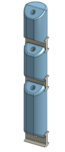
Finger wrap with joint strain relief: wings distribute stress, side flaps enable modular fit, extra segment spacing prevents bunching.
Electronics & Dual-Modality Sensing
Capacitive Stack & PCB Architecture
System Architecture
The capacitive sensing system employs a row-column grid addressing scheme to minimize pin count while maintaining spatial resolution. Exposed touchpad matrix on the PCB surface forms one capacitor plate; conductive layer in the skin forms the opposing plate. Applied force compresses dielectric (foam layer), decreasing capacitor distance and increasing capacitance. Differential measurements across the grid localize force application.
Signal Chain
Frontend multiplexing: Analog mux sequentially connects each row-column intersection to ADC input; reduces 400-node array (20×20 grid) to manageable channel count
Capacitive ADC (24-bit): High-resolution conversion enables detection of small capacitance changes (~pF range); dramatically outperforms ESP32's 8-bit ADC (early prototypes); resolution improvement essential for characterizing subtle force gradients
RP2040 acquisition: Microcontroller orchestrates mux scanning, ADC readout, and data packaging; dual-core architecture enables parallel sensor acquisition and communication
RS-485 bus: Robust multi-drop industrial protocol for noise immunity; enables daisy-chaining multiple skin panels across robot; differential signaling reduces susceptibility to EMI in actuator-heavy environment
Layout Considerations
Sensor area isolation: Touchpad region separated from digital circuitry via ground plane partitioning; reduces switching noise coupling into sensitive capacitive measurements
Guard rings: Grounded traces surround sensor pads to minimize parasitic capacitance and crosstalk; critical for accurate differential measurements
Power regulation: LDO provides clean, low-noise supply for ADC analog section; separate digital/analog power domains prevent supply rail bounce from corrupting measurements
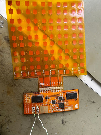
Capacitive PCB: left half shows touchpad grid (row-column addressing); right half contains mux, 24-bit ADC, RP2040, RS-485 transceiver, and power regulation.Resistive Stack (Velostat) & PCB Design
Operating Principle
Velostat (pressure-sensitive conductive polymer) exhibits resistance decrease under compression. Sandwich architecture: copper electrode layer, Velostat sheet, second copper layer. Applied force compresses Velostat, increasing contact area and reducing resistance. Voltage divider configuration converts resistance change to measurable voltage; ADC quantifies force magnitude.
Advantages & Limitations
Pros: Simple readout circuit (no specialized ADC required); direct DC measurement; low component count; fast response time
Cons: Shorts at flex points where copper layers contact; pressure distribution sensitivity (force location affects reading); wiring path creates mechanical interference; requires careful strain relief
Design Requirements
Electrode isolation: Copper layers must remain separated except at intended sensing points; achieved via precision Velostat cutting with gaps at joint locations
Strain relief: Wiring routed through low-stress regions (finger sides); slack loops at joints prevent wire breakage during flexion; critical for long-term reliability
Guard traces: Grounded traces between signal lines reduce crosstalk; essential when routing multiple resistive sensors in parallel
ESP32 Integration (Early Prototypes)
Initial resistive builds used ESP32 for ADC acquisition. While functional for proof-of-concept, 8-bit resolution proved insufficient for characterizing subtle force gradients. Later prototypes integrated higher-resolution ADCs for parity with capacitive system's 24-bit performance.
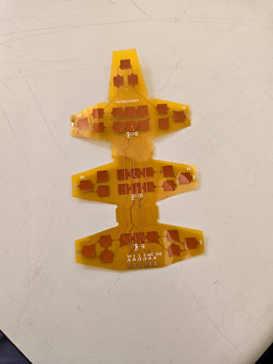
Resistive Velostat stack: copper electrode pads sandwich pressure-sensitive polymer; gaps at joints prevent shorting during flexion.
Characterization & Testing Protocols
Standardized Testing Procedure
Setup & Calibration
Assemble stack: Layer silicone skin, foam dielectric, sensor PCB according to design specification; verify mechanical alignment and electrical connections
Connect to logger: Arduino or RP2040 configured for multi-channel time-series acquisition; sampling rate ≥100 Hz to capture transient responses
Zero baselines: With no applied force, record 30-second baseline for each channel; calculate mean and standard deviation; establish noise floor and drift characteristics
Mark test points: Label 5-8 spatial locations on skin surface; ensures consistent force application across trials for repeatability analysis
Force Application Protocol
Systematic force progression to characterize dynamic range and linearity:
10g force: Apply calibrated 10g mass to labeled point; hold for 2 seconds; record sensor response; remove mass; wait 3 seconds for relaxation; repeat 3 trials
25g force: Repeat procedure with 25g mass; three trials per point
50g force: Repeat with 50g mass; approach sensitivity upper limit for soft sensors
100g force: Maximum test force; three trials; check for permanent deformation or sensor saturation
Data Analysis
Rise time: Duration from force application to 90% steady-state reading; quantifies sensor responsiveness
Drift: Change in sensor reading during sustained force application; indicates creep or charge leakage
Hysteresis: Difference between loading and unloading curves; capacitive systems showed ~±1 unit hysteresis due to foam viscoelasticity
Spatial selectivity: Signal magnitude at target sensor vs. adjacent sensors; validates independence of array elements
Noise characterization: RMS noise from baseline recordings; signal-to-noise ratio at each force level
Quantitative Observations & Failure Modes
Capacitive System Performance
Force detection: Successfully detects forces across 10-100g range; distinguishes spatial location of applied force within grid resolution
Latency: ~2-second delay from force application to steady-state reading; attributed to foam viscoelastic response and ADC averaging
Hysteresis: Approximately ±1 unit difference between loading and unloading curves; foam compression/recovery asymmetry creates path-dependent behavior
Resolution limit: 24-bit ADC provides excellent sensitivity; noise floor determined by foam dielectric stability rather than electronics
Resistive System Challenges
Intermittent shorts: Copper layers contact at bend points despite Velostat gaps; manifests as sudden resistance drops to near-zero; requires improved isolation strategy
Wiring path sensitivity: External wing routing concentrates stress on copper traces; strain relief critical but difficult to implement without increasing thickness
Inconsistent readings: Front-side pressure creates readings, but back-side contact also triggers response; poor spatial selectivity compared to capacitive approach
Handling artifacts: Grasping finger during manipulation changes baseline resistance; Velostat sensitivity to non-targeted forces reduces signal quality
Sensitivity Boundaries
Lower limit <30N: Forces below ~30 Newtons produce inconsistent readings; insufficient foam compression to overcome noise; requires pre-load or stiffer dielectric
Upper limit ~100N: Forces above 100N cause foam bottoming-out; sensor saturates; potential permanent deformation at extreme loads
Dynamic range: Approximately 3:1 useful range (30-100N); improvement requires multi-layer foam with progressive stiffness
Capacitive time-series: force detection confirmed with ~2s latency and ~±1 unit hysteresis; 24-bit ADC resolution enables subtle gradient measurement.Resistive finger data: intermittent shorts at bends create noise spikes; wiring path interference evident; strain relief inadequate for reliable operation.
Prototype Evolution: P1 → P5
Five major prototype iterations explored different sensing modalities, materials, and integration strategies. Each build informed subsequent designs through systematic failure analysis and performance characterization.
P1 - Shear Capacitance Nib Prototype
Design: Ecoflex 00-30 elastomer layer with copper tape nodes positioned at nib corners; ESP32 "touch" ADC pins for capacitive readout; 5×5 large-scale nib array for proof-of-concept.
Results: Successfully detected shear direction via differential capacitance across four corners; Ecoflex elasticity adequate for displacement sensing; demonstrated viability of multi-axis force resolution.
Abandonment rationale: Electrode density constraints insurmountable at target 20×20 resolution (1,600 connections); routing complexity and crosstalk exceeded PCB fabrication capabilities; shear sensing unexplored in favor of simpler normal force detection.
P2 - Rough Capacitive Sensing
Design: Copper tape electrodes separated by rigid commercial foam (salvaged from lab supplies); basic proof-of-concept without custom materials.
Results: Partial success: capacitance change detected under compression, but foam rigidity limited sensitivity; insufficient deformation at low forces (<50g); served as validation for pursuing custom foam formulation.
Lessons: Confirmed capacitive sensing viability; identified foam compliance as critical parameter; motivated Flex-Foam VIII selection and ratio optimization.
P3 - Layered Silicone + Optimized Foam
Design: Dragon Skin FX Pro outer shell (1mm); optimized Flex-Foam VIII dielectric (1:1.6 ratio); copper tape electrodes; paper backing; silicone glue bonding; Arduino data acquisition.
Results: Force detection across skin surface confirmed; spatial localization within grid resolution achieved; however: delayed response (~2s latency) due to foam viscoelasticity; hysteresis (~±1 unit) on loading vs. unloading; ADC resolution (24-bit vs. ESP32 8-bit) critical for characterization.
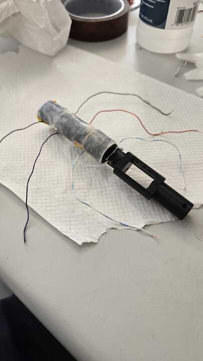
Design: Velostat sheet cut to finger segment geometry with gaps at joints; copper tape adhered via silicone glue; Dragon Skin outer layer; wires routed from external wings to ESP32 ADC pins; resistance measurement via voltage divider.
Results: Inconsistent readings plagued by multiple failure modes: shorts between sensing pads when copper layers contacted at flexion points; wiring path interference where external wing routing created stress concentrations; backside sensitivity where finger rear contact triggered readings (poor spatial selectivity); handling artifacts from grasping during manipulation.
Root causes: Inadequate electrode isolation at joints; insufficient strain relief in wiring; Velostat's omnidirectional pressure sensitivity (lacks spatial discrimination of capacitive approach).
P5 - Revised Capacitive Sensing
Design: Hybrid architecture: Velostat resistive layer for improved force coupling; copper tape beneath Velostat; second copper layer on paper substrate above; Arduino logging; attempted integration of lessons from P3 and P4.
Results: Confirmed force response; limited sensitivity below ~30N (insufficient compression to overcome noise); eventual short circuit due to electrical design deficiencies (inadequate isolation between layers).
Status: Demonstrated incremental improvement but fundamental challenges remain: dynamic range constraints, isolation difficulties, and system integration complexity require further iteration beyond P5.
Results, Contributions & Future Directions
Achieved Outcomes
Manufacturing workflows: Validated repeatable protocols for 1mm silicone injection molding (luer-lock system, 4-vent architecture, degassing procedures) and porous foam casting (1:1.6 ratio optimization, expansion factor calculations, release agent techniques)
Material characterization: Established Dragon Skin FX Pro as optimal outer layer (Shore 2A, 763% elongation, 500 psi tensile strength, −60°C to 230°C thermal range, platinum-cure safety); optimized Flex-Foam VIII as compliance layer (8 lb/ft³ density, 1:1.6 A:B ratio for ideal porosity)
High-density design: CAD for 20×20 nib arrays achieving 16 receptors/cm² (exceeding human fingertip density); strain-relieved finger wraps preventing joint-induced tearing; modular interlocking architecture for scalable coverage
Dual-modality sensing: Capacitive system (24-bit ADC, row-column grid, RP2040 + RS-485) characterized with ~2s latency, ~±1 unit hysteresis, 30-100N dynamic range; resistive system (Velostat + copper) revealing failure modes (shorts at bends, wiring interference, poor spatial selectivity)
Failure mode analysis: Documented electrode density limitations (1,600 connections impractical for nib approach); identified foam viscoelasticity as latency source; established strain relief as critical for joint-crossing sensors
Quantitative Performance Metrics
Silicone layer: 1mm thickness, 10×10 cm sheets, 40-minute cure, bubble-free via vacuum degassing
Nib resolution: 400 nibs over 100 cm², 16 receptors/cm² (4 electrodes per nib), 60% above human fingertips
Capacitive sensing: 24-bit resolution, ~2s response latency, ±1 unit hysteresis, 30-100N range
Cost: ~$85 silicone per 6-foot humanoid (1mm coverage); ~$36 foam trial kit for multiple prototypes
Next Steps & Future Work
Guard traces & shielding: Implement comprehensive EMI mitigation for capacitive arrays; active guarding to reduce parasitic capacitance; improve signal-to-noise ratio in actuator-heavy environments
FPC (Flexible Printed Circuit) integration: Replace copper tape with custom FPC tails at joints; enables strain-compliant wiring without shorts; reduces thickness vs. wire routing
Faster ADC/AFE: Upgrade from 24-bit Σ-Δ ADC to faster successive-approximation architecture; reduce latency from ~2s to <100ms; enable real-time control loops
Stretchier nib materials: Evaluate Formlabs Elastic 50A for improved recovery vs. Flexible 80A; balance increased compliance against potential sensitivity loss; optimize for high-cycle fatigue resistance
Multi-layer foam stacks: Progressive stiffness gradient (soft → firm) to expand dynamic range; prevent bottoming-out at high forces while maintaining low-force sensitivity
Machine learning for drift compensation: Neural network models to correct hysteresis and temperature-dependent behavior; enable long-term calibration stability
Integration testing on Mona: Full-humanoid deployment to validate thermal management, power distribution, data aggregation, and mechanical durability in operational scenarios
Broader Impact
This work establishes foundational manufacturing processes and design principles for bio-inspired robotic skin at humanoid scale. The combination of repeatable fabrication protocols, dual-modality sensing characterization, and systematic failure analysis provides a roadmap for future researchers pursuing tactile-enabled human-robot interaction. By documenting both successes (optimized material formulations, high-density nib designs) and failures (electrode routing constraints, wiring-induced shorts), I accelerate the field's progression toward robots with human-like touch sensitivity.